Pico Setup
As on the Pi, the first thing to do with the Pico is get some software onto it.
Warning
You are about to erase everything on your Pico W. If you’ve got any code saved on there that you want to preserve, take a copy of it first.
The first thing to load is a special MicroPython build which includes Pimoroni’s fabulous “plasma” library. One of the following should suffice, depending on your model of Pico:
- 2040-based Pico W
- 2350-based Pico 2W
For reference, I’ve used pimoroni-pico 1.21.0 on a Pico W, and
pimoroni-pico-rp2350 0.0.10 on a Pico Plus 2W, but you should probably just
grab the latest build for your specific board. The file should have a name
something like board-version-pimoroni-micropython.uf2.
Find a cable suitable for connecting your Pico to your computer, but don’t connect it just yet! Plug one end of the cable into your computer, then hold down the “BOOTSEL” button on the Pico while inserting the other end of the cable into the Pico. Continue holding the button for about a second after you’ve inserted the cable. This procedure puts the Pico into a mode where you can re-flash it.
Shortly after, you should see the drive “RPI-RP2” appear. Copy the
pimoroni-pico firmware you downloaded (the
board-version-pimoroni-micropython.uf2 file) to this drive. It
should take a few seconds to copy, then a brief time later you should see the
drive disappear again. This indicates the Pico has accepted the firmware and
has rebooted into MicroPython.
Unplug the Pico W from your computer, and plug it into your Raspberry Pi. Now run the bxflash application to copy the Blinken’ Xmas script to the Pico:
$ bxflash
Copying mqtt_as.py
Copying config.py
Copying blinkenxmas.py
Copying main.py
Copying leds.py
Copying animation.py
At this point all the software installation on both Pi and Pico is done. Time to move onto the hardware.
Wiring
Now it’s time to put your Pico together with the breadboard. You’re aiming for the following layout where the neopixel on the left represents the start of the 50 neopixel strip (connected to GPIO 15), and the strip on the right (connected to GPIO 16) represents the start of the 100 neopixel strip.

The power cables off the top of the board are deliberately separate. The wires on the left rails supply power to the neopixels. The wires on the right rails supply power to the Pico (via VBUS and ground). These should either be connected to separate rails of your supply, or entirely separate supplies. In the latter case, run a cable between the negative rails on each side of the breadboard to ensure everything has a common ground.
A momentary button connects the Pico’s RUN pin to ground so that we can easily hard-reset the Pico if the software locks up for any reason. Finally, GPIO 22 connects to a 330Ω resistor, then an LED, then ground to provide a crude means for the Pico to report status to us (by blinking the LED in various patterns).
Note
Why not use the LED built into the Pico? Or the reset button present on the Pico Plus 2W? Ultimately the Pico and its (bulky) power supply are going to be housed in some sort of box to keep small fingers from poking around near mains electricity. Unless that box is transparent, it’s going to be difficult to see the Pico’s own LED. Also, while “turning it off and on again” is certainly an option for resetting the Pico, a simple momentary button is even easier.
In my current setup, the reset button and status LED are combined into a single nice, big, illuminated button attached to the housing.
This is also the point where you will need to make sure your neopixel strips have some suitable connections to the breadboard. At its most basic, soldering some solid-core wire onto the terminals can work. However, where possible I’d recommend either purchasing sets with pins pre-soldered (although these can be quite difficult to come by), or buying a set of crimpers and connectors to make your own connectors (preferably with some heat-shrink for insulation):
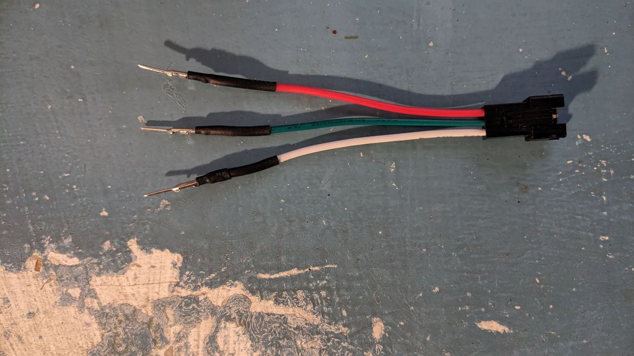
Ideally, you want your neopixel connector to stand off from the breadboard so that it can sit outside your box, and to be irreversible so that you can’t mix up the +5V and ground lines. Typically, wiring for WS2812 (3-pin) neopixels places the data pin in the middle with the +5V and ground lines either side. In the picture above, the +5V line is red, the data line is green, and the ground line is white. The connector on the right can only be mated one way around, so provided the connections on the breadboard are correct, you will be unable to connect your neopixel strip the wrong way around.
With the breadboard populated, wire the +5V and ground rails to the relevant connectors on your power supply.
Housing and installation
With the breadboard fully populated, it’s time to install everything in a box. Prepare a mains cable for the power supply, and install it through an appropriately sized cable gland in the box for strain relief. Attach the power supply to the interior of the box by whatever means is convenient. Typical plastic project boxes may have screw-mount points pre-moulded inside them, but it’s also fine to drill through most such boxes and attach screws to mount the power supply. Just be sure that any ventilation holes on the power supply remain uncovered.
Mount the breadboard within the box. Most breadboards have a self-adhesive backing that is convenient for this purpose. Again, ensure you do not cover ventilation holes on the power supply, and keep any bare conductors on the breadboard away from the power supply. Ideally, your box should be large enough to accommodate power supply and breadboard side by side, but if yours is not ensure there is adequate separation to avoid any shorts, and to allow free air flow over the power supply.
Make some holes for the neopixel connectors. Cable glands may be used here, but aren’t as important as for the mains cable which definitely requires strain relief.
I would recommend the following order for setting up the tree itself:
Locate the tree where you like, but ensure a power socket is reasonably nearby so that you’re not trailing mains cables across the floor
Decorate the tree with all the baubles and trinkets you want, except the neopixel strands
Add the neopixels strands
For each strand, start with the unconnected end at the top of the tree and wind it around in a spiral until you reach the bottom
Once all strands are on, re-arrange the bottom until the ends that you want to connect to the Pico are all gathered together
Use a cable tie to ensure the bottom of the strands stay together
Place your housing containing the power supply and Pico under the tree, and connect the strands to it